
Werkzeuge
Ersatzteile
Keine parts angegeben.
-
-
Greifen Sie nicht in die Schlitze, um den Regler anzuheben
-
Heben Sie den Regler nur von den Seiten an
-
Greifen Sie die Netzteile nicht an, um den Regler anzuheben
-
Haben ein Team von zwei Personen den Controller aus der Verpackung heben
-
Partner B (rechts): Halten G5000-Controller
-
Partner A (links): Entfernen Sie die Rückseite und mittlere Kissen
-
-
-
Partner A: Schieben Sie die Hände unter Plastikfolie und übernehmen G5000-Controller von Partner B
-
Partner B: Sorgfältig vordere Polster über bothe Seitenflansche gleiten - ein zu einer Zeit
-
-
-
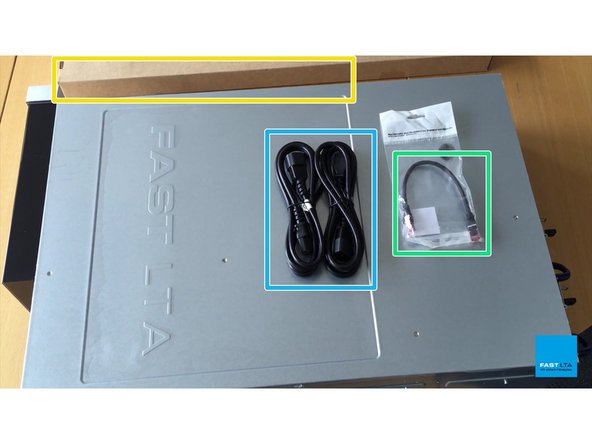
1 G5000-Controller
-
1 Loop-Kabel
-
2 Netzkabel
-
1 Satz von zwei Rack-Schienen mit Befestigungsschrauben
-
-
-
G5000-Controller Unboxing
-
-
-
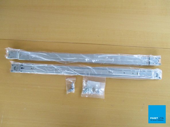
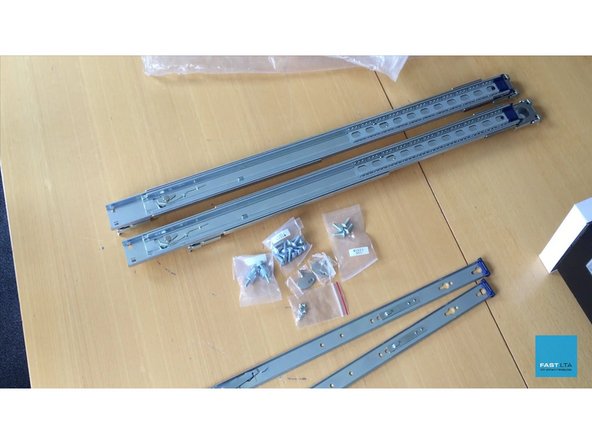
2 Rack Slides
-
Packung mit 2 Rack-Schrauben
-
2 G5000 Controller Bay Tasten
-
Packung mit 4 M5x15 Schrauben
-
Packung mit 12 M5x15 Schrauben
-
Packung mit 10 Stück M4x4 Schrauben
-
-
-
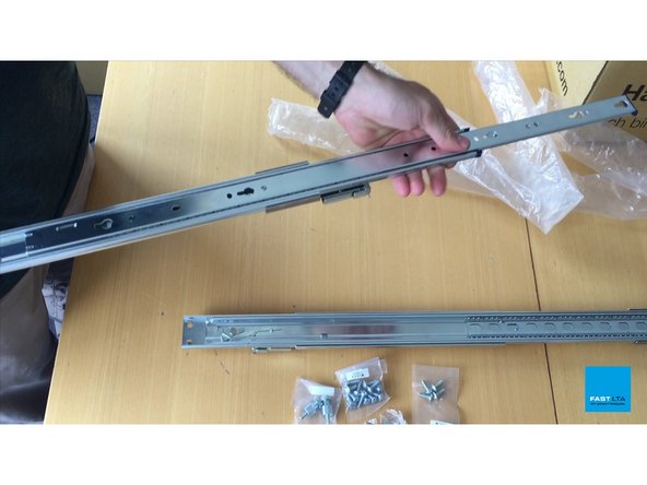
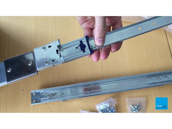
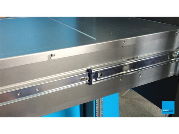
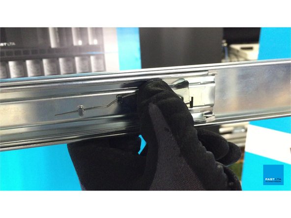
Ziehen Sie inneren Arm, bis die Sperre
-
Flip-Rack Schieben über und nach unten drücken, Hebel, um vollständig inneren Arm herausziehen
-
Wiederholen Sie für die zweite Rack-Schlitten
-
-
-
Rack-Schienen Berge Vorbereitung
-
-
-
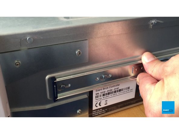
Platzieren Innenarm des Rack-Slide auf der Seite der G5000-Controller so, dass die Löcher in dem inneren Arm mit den Stiften auf der Contoller ausrichten
-
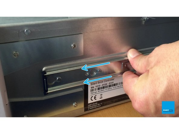
Schieben Sie den inneren Arm der Rack Slide auf der Rückseite des Controllers, um sie in Position zu verriegeln
-
-
-
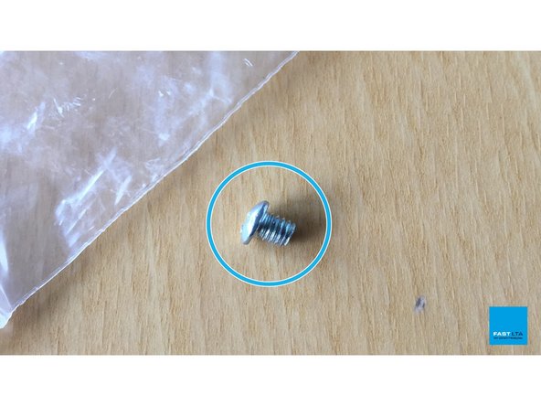
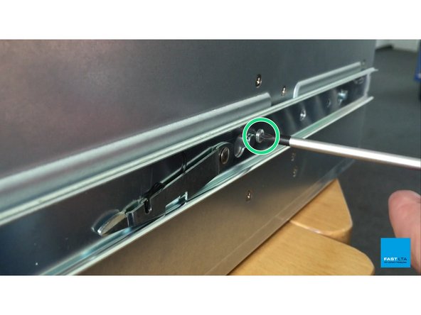
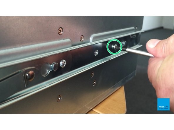
Verwenden Sie die mitgelieferten Schrauben M4x4
-
Fixieren Sie Innenarm der Rack-Schiene mit je zwei Schrauben, wie in den Bildern gezeigt
-
Wiederholen Sie die Schritte 1 und 2 für die andere Seite des G5000-Controller
-
-
-
G5000-Controller Rack-Slides Berg
-
-
-
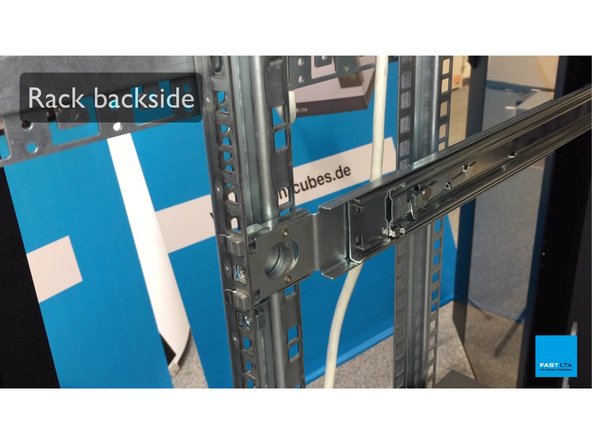
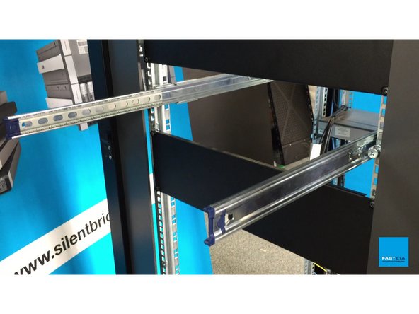
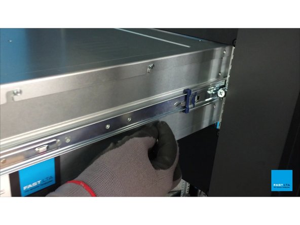
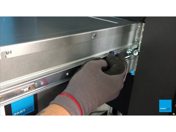
Legen Sie die Rückseite Stifte der äußeren Arme der Rack Schieben Sie in Ihrem Rack
-
Ziehen Sie den runden Hebel die vorderen Stifte klammern sich an Ihrem Rack zu lassen zurück
-
-
-
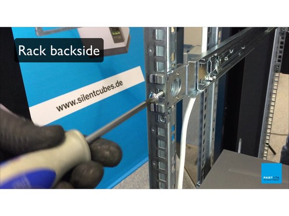
Verwenden Sie M5x15 Schrauben
-
Lock-Rack-Schienen auf Rack-Rückseite mit Schrauben, wie gezeigt
-
-
-
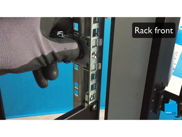
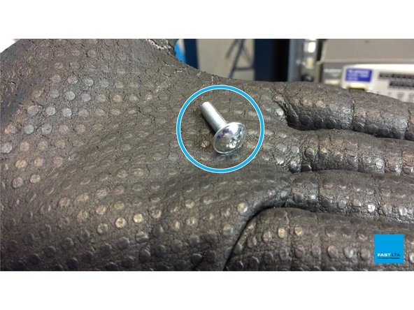
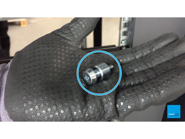
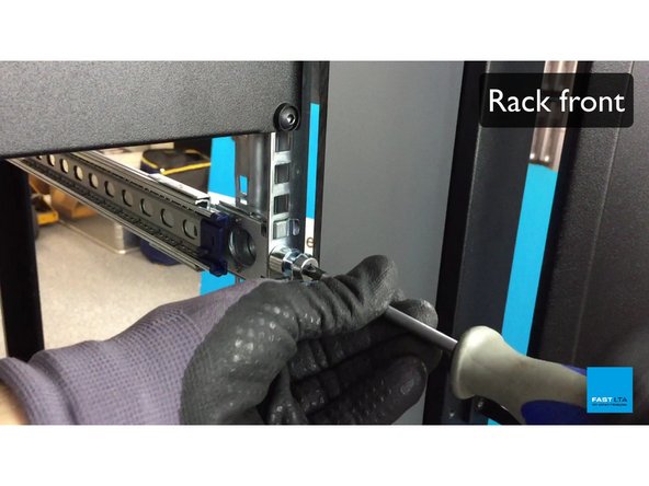
Verwenden Sie Rack Mount Bolt
-
Lock-Rack-Slide auf Rack-Vorderseite mit Schrauben, wie gezeigt
-
-
-
Rack-Schienen Rack Mount
-
-
-
Ziehen Sie die äußeren Arme der Rack-Schienen heraus, die auf Ihrem Rack montiert wurden
-
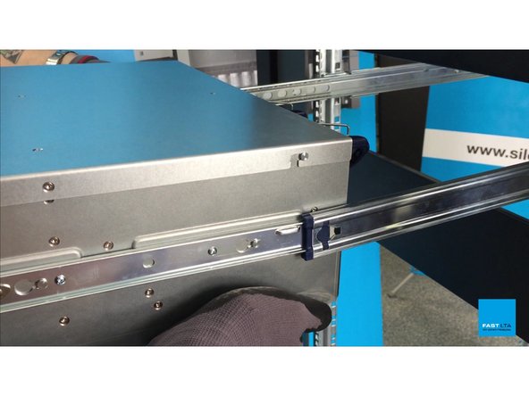
Richten Sie die inneren Arme, die mit den äußeren Armen zu Ihrem G5000-Controller angebracht sind
-
-
-
Schieben G5000-Controller auf halbem Weg in das Rack, bis der Hebel an den inneren Arm Verriegelungen
-
-
-
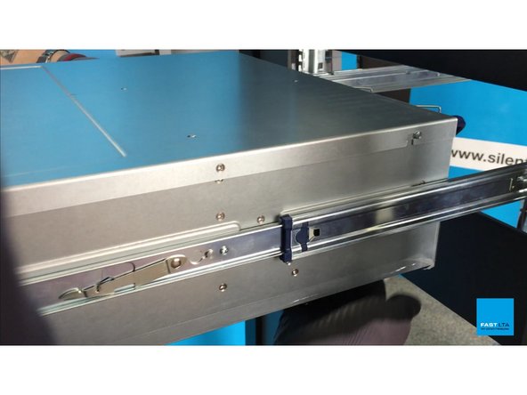
Lösen zweiten Hebel im Rack und weiterhin die G5000-Controller in das Rack Schiebe
-
-
-
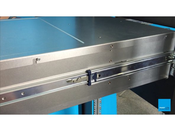
Schieben Sie G5000-Controller in das Rack, bis beide Rack-Flansche eingeklinkt haben
-
-
-
G5000-Controller Rack Mount
-
-
-
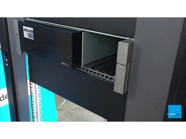
Schließen Sie das mitgelieferte Loop-Kabel an
-
Dieses Kabel verbindet Shelf und den Serverteil des Controllers
-
Wenn das Kabel nicht verstopft ist, zeigt das Display weiterhin "Inbetriebnahme"
-
Bei nicht angeschlossenem Kabel ist eine Kommunikation mit der Shelf nicht möglich
-
-
-
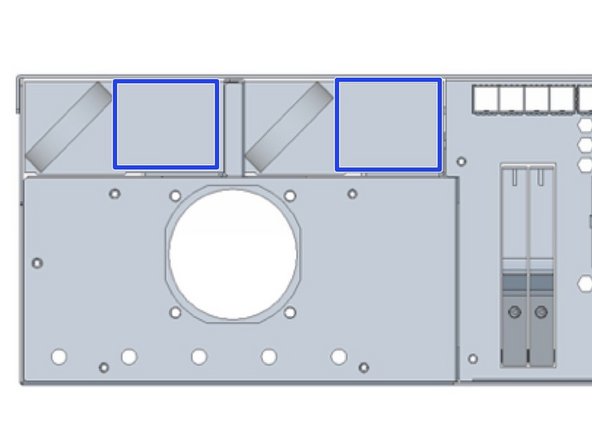
Management und Daten darf nicht im selben Subnetz sein
-
Management und Daten können zu einer Schnittstelle später kombiniert werden
-
Verbinden Sie 1GB Ethernet mit dem Management-Port für die Konfiguration über WebUI
-
Schließen Sie einen 1-GB-Ethernet-Anschluss an den IPMI-Port an, um die Hardware zu überwachen und auf Service zuzugreifen.
-
Verbinden Sie FibreChannel oder 10GB Ethernet Kabel mit dem Datenport (abhängig von der bestellten Hardware)
-
-
-
Starten Sie Ihren Controller, indem Sie die Stromkabel anschließen
-
-
-
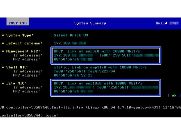
G5000 versucht, IP-Adressen über DHCP auf Management- und Datenschnittstellen zu empfangen
-
Wenn kein DHCP-Server gefunden werden kann, wird G5000 die Fallback-IP-Adressen wie folgt zuweisen
-
Verwaltung: 192.168.1.1
-
Daten: 192.168.2.1
-
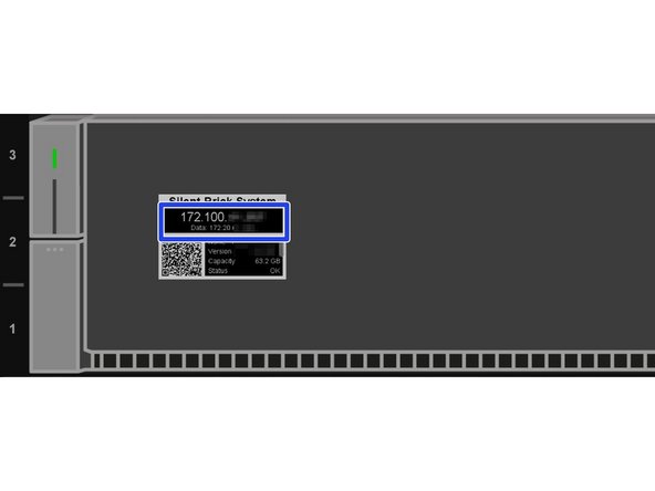
Die zugewiesenen IP-Adressen können über ...
-
... G5000 EPaper Display
-
... Konsolenausgabe überwachen
-
-
-
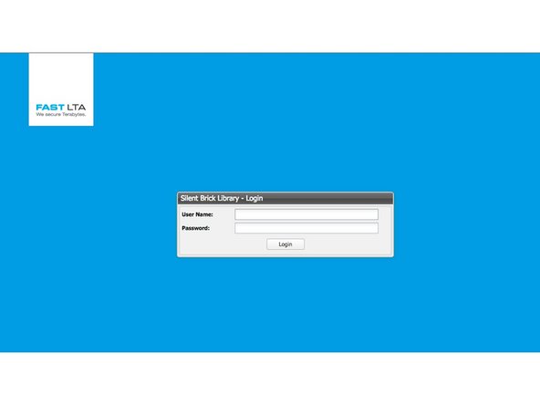
Öffnen Sie das Webinterface über die Management-IP "https://<ip> /
-
Standardbenutzer: admin
-
Standardpasswort: adminadmin
-
-
-
Öffne deinen Webbrowser
-
Verbinden mit https://<management-ip>
-
Melden Sie sich mit Ihrem Benutzernamen und Passwort an
-
Standardbenutzer: admin
-
Standardpasswort: adminadmin
-
-
-
Navigieren Sie zu Einstellungen -> Netzwerk
-
Hostname und Domäne bearbeiten
-
Umschalten zwischen Management- und Daten-IP-Konfiguration
-
Richten Sie Ihr Datennetz ein
-
Richten Sie Ihr Management-Netzwerk ein
-
Daten und Management darf nicht im selben Subnetz sein
-
Um ein Gateway einzugeben, müssen beide Schnittstellen zuerst in manuelles IP geändert werden
-
Richten Sie Ihre IPMI-Adresse ein
-
-
-
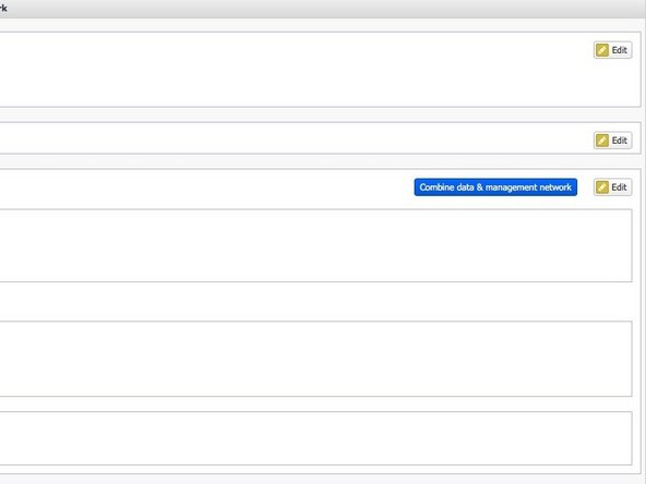
Netzwerkkombination ist sinnvoll, wenn sich Management und Daten in einem Subnetz befinden sollen
-
Um Ihre Management- und Datennetzwerke zu kombinieren, klicken Sie auf Kombinieren Sie Daten- und Verwaltungsnetzwerke
-
Die IP-Konfiguration wird von der Management-Schnittstelle auf Ihre Datenschnittstelle übertragen
-
-
-
Navigieren Sie zu Einstellungen -> Sonstiges
-
Richten Sie Ihre Zeitserver ein
-
-
-
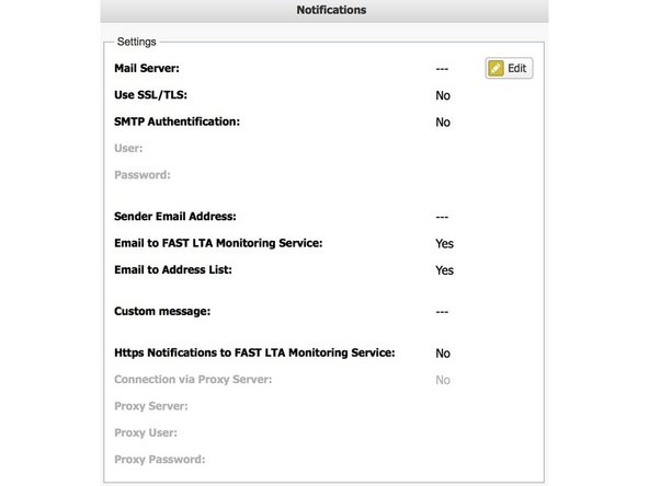
Navigieren Sie zu Einstellungen -> Benachrichtigungen
-
Richten Sie Ihre Benachrichtigungseinstellungen ein
-
Um die FAST LTA Monitoring-Unterstützung zu nutzen, ...
-
... eine gültige externe Adresse als Absender verwenden
-
... markieren Sie das entsprechende Kontrollkästchen
-
HTTPS-Benachrichtigungen sind optional und können in Gehäuse verwendet werden, wenn Mail-Relaying nicht erlaubt oder möglich ist.
-


Rückgängig: Ich habe diese Anleitung nicht absolviert.
2 weitere Nutzer haben diese Anleitung absolviert.

Team
